Keypad Operating Procedure
|
IMPORTANT!
See Appendix 3 for recommended startup procedures involving Zero Tare, Max Tare, and Altitude Adjustment. Following these procedures will provide optimal accuracy and control.
|
The eFlo system is equipped with a pressure and flow rate alarm (high and low), flow rate totalizer, and integrated valve control. The unit can be operated in either manual or automatic mode for flow rate control. This section of the manual provides an explanation of the basic menu navigation through the keypad as well as how the unit is operates including: valve control modes, flow limit control, flow alarming, flow totalizing, and programming of the unit.
|
IMPORTANT!
For best long term results, it is recommended that pressure be maintained on the flow meter at all times. Pressure can be maintained when the shut off solenoid/valve is downstream from the outlet of the meter. This will ensure long term calibration and accuracy.
|
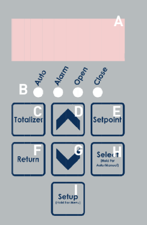
The figure below shows the layout of the flow control panel on the Keypad eFlo 2.0 unit. An explanation of the panel’s components is provided as well.The panel layout will be referenced further in this section.
|
Figure 1 - eFlo 2.0 LED Flow Control Panel Layout |
A – LED display By default, the LED display is used to display the current flow. The LED display can also be used to show the totalizer value, current setpoint, and Setup menu options with associated settings. During active alarms, alarm status messages may also be displayed.
B – Status indicators These four lights come on in various situations: Auto: When lit, the eFlo is in Auto valve control mode. When not lit, the unit is in Manual valve control mode. Alarm:When lit, an alarm is active. See Alarms section for more information. Open: When lit, the valve is driving open. Close: When lit, the valve is driving closed.
C – Totalizer button D – Up button E – Setpoint button F – Return button G – Down button H – Select button I – Setup button
|
|
|
|
