23. Cold Junction Trim
The instructions for performing the Cold Junction Trim on the inputs will depend on the firmware level of the instrument that you have. You can determine the firmware version be checking menu option 13 Revision Display. The number to the right of the first line, “Main Processor”, will be the firmware level. Please select the instructions below based on the firmware level of the instrument.
Firmware revision 1.09 or below

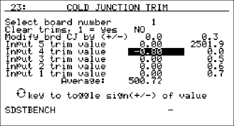
This screen displays the setup information to trim the cold junction value of each board. Highlight the first line (“Select board number”), enter the desired board number to trim, then press the Enter key. The acceptable values for the board number are: 1 – 8. Any number entered over 8 will default to 8 and any number entered less than 1 will default to 1. Press the down arrow key to highlight the next line (“Clear trims, 1 = yes”). This line will allow an operator to clear out the previous cold junction trims for each input. Enter a 1 for “yes” (clear input trims) or a 0 for “no” (do not clear input trims), and press the Enter key. Note – Clearing the trims will only clear out the cold junction trims for the selected board. If the operator selected 1 (“yes”), the trims will be cleared once the Enter key has been pressed. Press the down arrow key to highlight the “Modify brd CJ by (+/-)” line. This will allow an operator to modify a board’s overall cold junction value. See the section To Perform a Cold Junction Calibration below for details on performing the cold junction calibration. Enter the desired cold junction trim value, and, if necessary, press the circular arrow key to toggle the sign of the cold junction value. Note – Pressing the circular arrow key will also toggle the “Clear trims” value between “yes” and “no”. Press the Enter key to begin the cold junction trim. When the trim has finished, the line will display 0.0, instead of the value that was entered. This is because the offset is actually a recalibration of the board and after the calibration process there will be no offset. If there are any trim values for the inputs, they must be cleared before modifying the cold junction value for the board. If an operator attempts to change the cold junction value without clearing the trim values, the “Modify brd CJ by (+/-)” line will display “Clr Trims”. To set each individual input’s trim value, press the down arrow key to highlight the specific input. The inputs are listed from top to bottom starting with input five and ending with input one. Enter the desired trim value, and, if necessary, press the circular arrow key to toggle the sign of the trim value. Press the Enter key to set the new trim value. The input trim values range from –18.00 to 18.00. Note – The overall Cold Junction value is modified by adding or subtracting a value to the current value. The individual input trim values are set to the entered value.
Firmware Revision 1.10 and above
Depending on the revision level of the internal input board, the screen will resemble one of the two following screens. One version uses one Cold Junction Trim value that is applied to the entire board. The other version uses a unique Cold Junction Trim value for each of the five inputs on that board. The instrument will automatically determine which screen should be displayed based on the internal boards that are installed inside it.
Input Board Version 1.07 and below

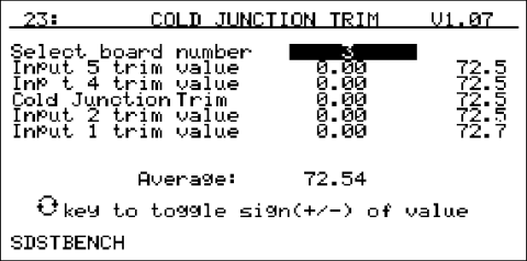
This screen displays the setup information to trim the cold junction value of each board. Note – Since the Cold Junction screen’s functionality changes slightly based upon the input boards’ version, it is important to know which version of boards is in the SDS Data Logger. The input board version number will be displayed in the top right corner. Highlight the first line (“Select board number”), enter the desired board number to trim, then press the Enter key. The acceptable values for the board number are: 1 – 8. Any number entered over 8 will default to 8 and any number entered less than 1 will default to 1. The next section of the menu screen will look like the following:
Input 5 trim value
Input 4 trim value
Cold Junction Trim
Input 2 trim value
Input 1 trim value
The line for “Input 3 trim value” is shown as “Cold Junction Trim” because this line controls the actual cold junction trim. Input boards with version 1.07 and below only contain one thermister per board; so only one cold junction trim will be needed.
See the section To Perform a Cold Junction Calibration below for details on performing the cold junction calibration. The “Cold Junction Trim” will adjust all of the inputs simultaneously. Any trim value entered for inputs 5, 4, 2, or 1 will not be reset during the cold junction trim; therefore, those inputs would be even more offset after the cold junction trim. For best results, perform the cold junction trim first, then perform any necessary input trims. Press the down arrow key to highlight the “Cold Junction Trim” line. This will allow an operator to modify a board’s overall cold junction value. Enter the desired cold junction trim value, and, if necessary, press the circular arrow key to toggle the sign of the cold junction value. Press the Enter key to begin the cold junction trim. While the system is working, the word “Busy” will appear below the “Input 1 trim value” line. When the trim has finished, “Busy” will disappear. To set each individual input’s trim value, press the down arrow key to highlight the specific input. The inputs are listed from top to bottom starting with input five and ending with input one (except for input three). Enter the desired trim value, and, if necessary, press the circular arrow key to toggle the sign of the trim value. Press the Enter key to set the new trim value. Note – The overall Cold Junction value, as well as any trim value, is modified by adding or subtracting a value to the current value.
Input Board Version 1.08 and higher

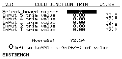
The functionality of the Cold Junction Trim menu screen is similar to the Cold Junction trim for the input board versions 1.07 and below. The difference is that the new boards have five thermisters, instead of only one, so each board must have five cold junction trims performed. The middle of the screen will look like the following:
Input 5 trim value
Input 4 trim value
Input 3 trim value
Input 2 trim value
Input 1 trim value
See the section To Perform a Cold Junction Calibration below for details on performing the cold junction calibration. Press the down arrow to highlight the input to be trimmed. Enter the desired cold junction trim value, and, if necessary, press the circular arrow key to toggle the sign of the cold junction value. Press the Enter key to begin the cold junction trim. While the system is working, the word “Busy” will appear below the “Input 1 trim value” line. When the trim has finished, “Busy” will disappear.
Firmware Revision 1.11 and above
With Firmware revision 1.11, the title of the menu option 23 has become “CJ Calibration” instead of “Cold Junction Trim”.
To Perform a Cold Junction Calibration
The user will need a thermocouple calibrator capable of outputting a thermocouple signal to calibrate the cold junction value of the data logger. The user will need to connect the calibrator to one of the inputs on the data logger for the channel that will be calibrated. It is recommended to let everything (calibrator and datalogger) sit for approximately thirty minutes to allow the temperature to achieve equilibrium. Set up the calibrator for the specific thermocouple type of the thermocouples in the datalogger, i.e. type K, type J, etc. Then, source a specific temperature, like 1000 °F to the connected input. It is recommended that the actual temperature used be similar to an appropriate process temperature. For example, if your equipment normally operates at 1700 °F, then perform the cold junction calibration using a 1700 °F signal.
Firmware Version 1.09 and below
The user can source temperature to any one of the inputs, since the cold junction value is separate from the input trim values, even though there is only one thermister per board. If the temperature being sourced does not match the temperature displayed on the screen, the user will need to adjust the cold junction value (“Modify brd CJ by (+/-) line) to match. After the cold junction value has been modified, the user will be able to modify any of the input trims, if necessary.
Firmware Version 1.10 and above
Input Board Version 1.07 and below
The user will want to source the temperature to input three, since input boards with a version of 1.07 or earlier only have one thermister, so the cold junction calibration will apply to the whole board. If the temperature being sourced does not match the temperature displayed on the screen, then the user will need to adjust the cold junction trim value to match. After the cold junction value has been modified, the user will be able to adjust the trim values for inputs one, two, four, and five, if necessary.
Input Board Version 1.08 and above
The user will have to source the temperature to all five inputs, since input boards with a version of 1.08 or later have five thermisters per board, one for each input, so the cold junction calibration will have to be made to each input separately. If the temperature being sourced does not match the temperature displayed on the screen, then the user will need to adjust the input trim value to match.