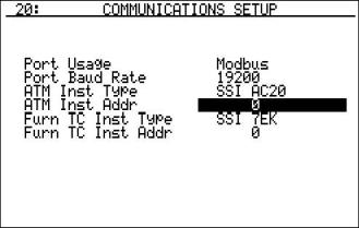
Communications Setup – Menu Page 20
The menu page will allow the user to set up the communications settings for the PGA.
The Port Usage determines how the PGA will communicate. The options are either RS485 Host Port or Modbus. These can be changed either by pressing the circular arrow key to cycle through the options, or by entering a number which corresponds to the option’s position in the list, where RS485 Host Port is at position 0, and Modbus is at position 1.
The Port Baud Rate determines how fast the PGA will communicate. The options with the position number are:
| Position | Rate |
| 0 | 1200 |
| 1 | 2400 |
| 2 | 4800 |
| 3 | 9600 |
| 4 | 14400 |
| 5 | 19200 |
| 6 | 28800 |
| 7 | 38400 |
| 8 | 57600 |
| 9 | 76800 |
| 10 | 115200 |
| 11 | 230400 |
| 12 | 460800 |
| 13 | 921600 |
To change the baud rate, press the circular arrow key until the desired option is reached, or enter in the position number from the list above and press Enter to select the desired option.
The ATM Inst Type is the make and model of the instrument that will be supplying the PGA with information on: probe temperature, probe millivolts, and COF/PF. The options with the position number are:
| Position | Type | Description |
| 0 | SSI AC20 | Super Systems AC20 |
| 1 | Yoko 750 | Yokogawa 750 |
| 2 | UDC 3300 | Honeywell UDC 3300 |
| 3 | DP 1 Mod | Marathon Sensors DualPro - Modbud Protocol Loop 1 |
| 4 | DP 2 Mod | Marathon Sensors DualPro - Modbus Protocol Loop 2 |
| 5 | 9200 lp | Super Systems Model 9200 Loop 1 |
To change the instrument type, press the circular arrow key to cycle through the options, or press the option’s position number and press Enter.
The ATM Inst Addr is the address of the ATM Inst. To change the address, enter the new value and press Enter. The values can range from 0 to 250.
The Furn TC Inst Type is the make and model of the instrument that will be supplying the PGA with information on furnace temperature. If there is no instrument associated with this input, the PGA will use the value from the probe temperature (ATM Inst Type) as the furnace temperature. The options with the position number are:
| Position | Type | Description |
| 0 | SSI 7EK | Super Systems 7EK |
| 1 | Yoko 750 | Yokogawa 750 |
| 2 | UDC 3300 | Honeywell UDC 3300 |
| 3 | DP 1 Mod | Marathon Sensors DualPro - Modbus Protocol Loop 1 |
| 4 | DP 2 Mod | Marathon Sensors DualPro - Modbud Protocol Loop 2 |
| 5 | 9200 lp1 | Super Systems Model 9200 Loop 1 |
| 6 | 9200 lp2 | Super Systems Model 9200 Loop 2 |
| 7 | 9200 lp3 | Super Systems Model 9200 Loop 3 |
| 8 | 9100 lp1 | Super Systems Model 9100 Loop 2 |
| 9 | SSI_DO0 | Super Systems DAC Output Board Channel 0 |
| 10 | SSI_DO1 | Super Systems DAC Output Board Channel 1 |
| 11 | SSI_DO2 | Super Systems DAC Output Board Channel 2 |
| 12 | SSI_DO3 | Super Systems DAC Output Board Channel 3 |
To change the instrument type, press the circular arrow key to cycle through the options, or press the option’s position number and press Enter.
The Furn TC Inst Addr is the address of the Furn TC Inst. To change the address, enter the new value and press Enter. The values can range from 0 to 250.