Electrical Connections

WARNINGS:
All wiring MUST be in accordance with the National Electrical Code and any local codes, ordinances, and regulations.
Disconnect and lock out power before connecting the equipment to the power supply.
The device wiring should be in a separate conduit. Do NOT install wiring in any conduit or junction boxes with high voltage wiring.
 CAUTION:
-
Do NOT install the device suspended from the cable.
-
Avoid exerting excessive tensile force on the cable (e.g. tugging).
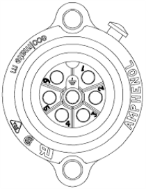
Housing: Amphenol Ecomate C016 30C006 100 12
Mating Connector: Binder 99-4218-00-07
NOTE: Mating connector also supplied.

PINOUT:
Pin 1: 24VDC ± 10%
Pin 2: 0VDC
Pin 3: Calibrate
Pin 4: Cycle
Pin 5: 4 – 20mA / RS232 Tx
Pin 6: 0 – 10VDC/ RS232 Rx
Centre: Housing / Probe Earth
NOTES:
-
Output pins 5 and 6 are both referenced to the power supply 0VDC (pin 2). Due to high current flow in the supply GND, when monitoring the 0 – 10VDC output (pin 6) it is recommended that a separate GND wire for the measurement system is taken from pin 2. This removes errors due to voltage drops in the power supply connections.
-
Assignment of output pins 5 and 6 selectable by altering the position of the jumper links on the PCB; refer to PCB Layout for details.