OPERATION -
The use of the DP2000 is somewhat dependent upon the application. Although they are fundamentally alike, the operation procedures are different for sampling heat treating furnaces and endothermic generators.
Flip the POWER switch to the on position. A green POWER ON light should illuminate indicating that the unit is turned on. The LED display should also illuminate showing “SSi” (Figure 1) followed by a dew point reading given in degrees Fahrenheit (Figure 2).
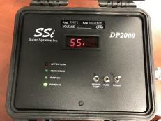
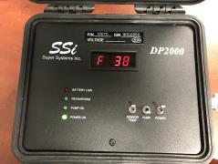
Figure 1 Figure 2
Connect a sampling tube/hose to the barb fitting located on the side of the DP2000 (Figure 3). Make sure that the hose or tubing fits over the fitting properly and does not allow air to leak into the sampling line. A tubing and filter assembly is supplied with the DP2000 (SSI P/N A20315 – Figure 5), which is designed to fit the hose barb properly. Also, make sure that the sample gas is flowing through the filter in the right direction. There is an arrow on the filter to indicate which direction the gas should flow (Figure 4).
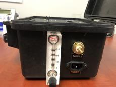
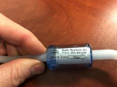
Figure 3 Figure 4
If the system from which gas is being sampled is under pressure, there should be visible flow in the flow meter. Adjust the flow through the meter using the adjusting knob on the meter.
If there is no visible flow after the sampling line is connected, the pump will need to be turned on to “pull” a sample through the DP2000. Flip the PUMP switch to turn on the sampling pump. The green PUMP ON light should illuminate when the pump is on (Figure 6). You should also be able to hear the pump running (depending on the noise level at your location).
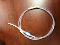
Figure 5
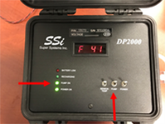
Figure 6
Regardless of the application, allow the DP2000 to sample gas for two to three minutes before recording any data. This assures that the sensor has achieved equilibrium in the sample gas. Also, make sure that the in-line filter (P/N 31033 or equivalent) is clean and functional. Not only will this ensure that the sample reading is not abnormally high (since soot tends to trap moisture), but it will also prevent soot and other contaminants from entering the unit and damaging the sensor.

Figure 7
The optimum flow rate of the sample gas should be between 1.5 and 2.0 cubic feet per hour (CFH) (Figure 7), although a flow rate as low as 1.0 CFH is acceptable. If the unit is reading less than 1.0 CFH, verify that there are no obstructions to the flow such as a clogged sample line or a poorly adjusted knob on the DP2000’s flow meter. If these conditions do not exist, the unit may need to be returned to SSI for replacement of the pump. The pump’s life is dependent upon how frequently it is used as well as the cleanliness of the sample gas. Insufficient filtration will significantly reduce the operating life of the pump.
Heat Treat Furnace Sampling: A gas sample may be extracted from a process using the built-in pump. The sample tube from which the sample is taken out of the furnace should extend into the furnace past the HOT face of the refractory. For accurate results, a designated sample port should be used to extract the sample. SSI offers a sample port assembly (part number 20263) which is ideal for this purpose. If a designated sample port is not available, then a clean “burn-off” port on an SSi Gold ProbeÔ, an industry leading oxygen sensor for atmosphere control, can be used. Readings taken from the burn-off port on a probe may be artificially high due to the presence of soot in the probe sheath.
Endothermic Generator Sampling: For applications under pressure, the pump should be switched off and the flow controlled by the small restriction valve on the flow meter. A flow rate between 1.5 and 2.0 CFH is ideal. The sample should be taken from the endothermic gas manifold after the gas has been cooled.
NOTE: Allow the sample port to blow out any soot and / or water before connecting the sample tube. Failure to do so will result in inaccurate readings and expose the sensor to potential damage.