Comparison Check
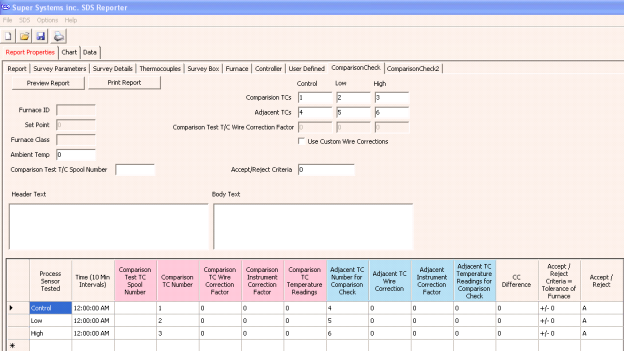
SDS Reporter includes two Comparison Check tabs, as shown in Figure 76 - Report Properties Comparison Check window. The two Comparison Check tabs perform the same function with different defined data sets.

Figure 76 - Report Properties Comparison Check window
The information for the comparison check is generated from several of the Report Properties fields.
|
Report Field |
Location in Tabs |
|
Time |
Chart Start Time |
|
Comparison Test T/C Spool Number |
Middle Left of Comparison Check |
|
Comparison T/C Number |
Top Right of Comparison Check |
|
Comparison T/C Wire Correction Factor |
Top Right of Comparison Check |
|
Comparison Instrument Correction Factor |
Thermocouples |
|
Comparison T/C Temperature Readings |
Records the temperature of the Comparison T/C |
|
Adjacent T/C Number for Comparison Check |
Top Right of Comparison Check |
|
Adjacent T/C Wire Correction |
Thermocouples, click View Offsets Used in Survey button* |
|
Adjacent Instrument Correction Factor |
Thermocouples, click View Offsets Used in Survey button |
|
Adjacent T/C Temperature Readings for Comparison Check |
Records the temperature of Adjacent T/C |
|
CC Difference |
Difference Between Comparison T/C and Adjacent T/C temperatures |
|
Accept/Reject Criteria = Tolerance of Furnace |
Set on Comparison Check Page, Middle Right |
|
Accept/Reject |
Dependent on A/R Criteria |
Table 2 - Location of Report Fields
*The offsets for the T/C Wire Correction can be adjusted solely for the purpose of the comparison by checking the box on the Comparison Check page labeled Use Custom Wire Corrections.
A header text and a body text can be put in the report. There are Preview Report and Print Report buttons in the top left hand corner of the Comparison Check page.
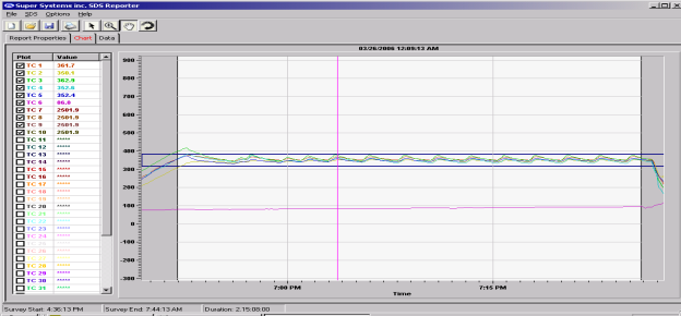
Figure 77 - Chart Tab) contains the charted information from the time specified on the survey. This tab is similar in design and function to the Real-Time chart (Figure 89 – Real-time Data screen). When the chart tab is active, the chart toolbar buttons also appear and these buttons can be used to zoom in on a section of the chart, pan the chart up, down, left or right, and refresh the chart back to its original values. The screen will display 2 horizontal lines that represent the high and low temperature tolerance levels based on the setpoint. This display will change based on the tolerance level and setpoint defined in the Report Parameters. For more information about the function of this screen, see the section “SDS à View Real-time Data.”

Note: checking or unchecking TCs on the Chart Tab will affect the Active TCs on the Report Properties – Thermocouples tab.
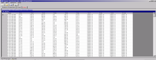
The Data Tab (Figure 78 - Data Tab) contains the data from each thermocouple for the each interval selected from the Load Survey Data screen (Figure 59 - Load Survey Data screen).

Clicking on the “Round this data off to the nearest degree” link will pop up a message box confirming the action (Figure 79 - Round data confirmation). The rounding only affects imported data. The data in the logged files will still contain data rounded to one decimal place. Clicking on the “Yes” button will round the data.
