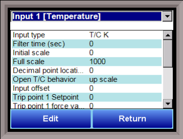
Analog Input Setup

The 9220 controller has three analog inputs. Each of the inputs comes with a factory default configuration dependent on the application. By default, input 1 is the control T/C input. The configuration can be modified prior to shipment to your facility or in the field by a technician or qualified/trained person with the proper security code.
Analog Input Terminals
Analog Input 1 – terminals 31 and 32
Analog Input 2 – terminals 29 and 30
Analog Input 3 – terminals 27 and 28
Input Type
The thermocouple type for most applications can be modified depending on your specific needs. Note - some of the inputs DO NOT allow the user to modify the Input type. To change the Input type, first select which input you want to change by selecting it in the pull-down at the top of the screen. The following is a list of the options:
B S 12.5 volts **
C T 781.25mv
E 2.5 volts 195.3125 mV
J 1.25 volts
K 78.125 mV
N 19.53125 mV
NNM 4-20 mA *
R 25 volts **
* - When the specified input type is selected, a 124 Ohm resistor will need to be placed on that specific input’s terminals for reading this selection. If resistor is not placed on input, then damage could occur to the board.
** - When the specified input type is selected, a jumper located inside the case will need to be placed on that specific input for reading this selection. If jumper is not placed on input, then damage could occur to the board.
Filter time
The filter time is a factory applied averaging tool used to help maintain steady control in high EMI environments. The filter time should not be adjusted without consulting SSI. Clicking on this value will display an input box from which the user can select a new value. The range is 0 to 32767.
Initial Scale
This is the initial scale value. This could also be referred to as the starting value. For example, the initial value is the value when 0 volts is on the selected input; or on a 4-20 mA input, it would be the value at the selected input of 4 mA. Clicking on this value will display an input box from which the user can select a new value. The range is –32768 to 32767.
Full scale
This is the full scale value for the analog input. This is preset for thermocouple types. Clicking on this value will display an input box from which the user can select a new value. The range is –32768 to 32767.
Decimal Point Location
This is the decimal point location value. This will affect the PV value and the location of the decimal when it is displayed. Clicking on this value will display an input box from which the user can select a new value. The range is 0 to 4.
Open TC Behavior
This is the open TC value. If the TC should fail, these are the options that the controller will display. The options are: upscale (will display the maximum scale number), down scale(will display the minimum scale point), one trip point (will use the trip point 1), and two trip points (will use which ever trip point is enabled).
Input Offset
The input offset value is algebraically added to the input value to adjust the input curve on read-out. The range is –32768 to 32767.
TRIP POINT EXPLANATION: Setting a trip point will force the value that the controller uses for calculations to a certain value as assigned by the operator. Once the Trip Point Setpoint is reached, the controller will begin reading the value as the Trip Point Force Value, regardless of what the actual value is inside the furnace. The Trip Point Direction allows the operator to choose whether the controller will alter its reading when the trip point is either above or below the setpoint.
Trip Point 1 Setpoint: This is the value at which the trip point will be activated, forcing the displayed value to the “force value” set below. This value must be something that the input can achieve.
Trip Point 1 Force Value: This is the value that the input will be forced to display when the trip point SP (set above) has been achieved.
Trip Point 1 Direction: This is the trip point 1 direction. Options are input above setpoint or input below setpoint.
If you choose input above SP then the PV for the selected input will need to transition above the Trip Point 1 SP value set above.

If you choose input below SP then the PV for the selected input will need to transition below the trip point SP value set above.

Example (when OPEN INPUT is set for 1 trip point):

In this example when this input's PV goes below 10 then the displayed value will be forced to ZERO. IF it cannot or does not go below 10 then the forced value will never happen.
Trip Point 2 Setpoint, Trip Point 2 Force Value, and Trip Point 2 Direction function identically to the above.
High Input Limit Setpoint
This is the setpoint for the high input limit. The range is –32768 to 32767.
High Input Limit Hysteresis
This is the hysteresis for the high input limit. The range is –32768 to 32767.
Custom Curve
This will allow the user to set the custom curve to use. The curves are set up through the Curve Entry menu option. The options are: None, Curve 1 – Curve 3.
T/C Correction Curve
This will allow the user to set the T/C correction curve to use. The curves are set up through the T/C Correction Curves menu option. The options are: None, Curve 1 – Curve 7.
The Return button will return the user to the menu screen.