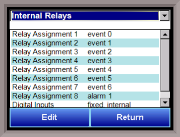
Relay Assignments

The 9220 controller has the option of using eight (on board) relay outputs, as well as an additional eight relay outputs (from Client instruments) for four additional modules. All of the relays have a positive common terminal and independent negative terminals. All of the relays are configured in a normally closed position except relay number eight, which has both a normally closed (NC) and a normally open (NO) terminal. These relays can be configured to work with events, alarms, loops, burnoff and alarm combinations.
Depending on the parameters selected within the Furnace & Port Setups of the 9220 controller, these outputs can be either (1) physical terminals on the 9220 controller or (2) bit references passed to an external instrument and/or PLC. In the second example, communications will have to be established between the PLC and 9220 controller (beyond the scope of this manual). Once a specific word has been assigned, bits within the word will turn On/Off in time with the 9220 controller.
Relay Output Terminals:
Relay Output 1 – terminals 7 and 8
Relay Output 2 – terminals 7 and 9
Relay Output 3 – terminals 7 and 10
Relay Output 4 – terminals 7 and 11
Relay Output 5 – terminals 7 and 12
Relay Output 6 – terminals 7 and 13
Relay Output 7 – terminals 7 and 14
Relay Output 8 – terminals 7 and 15 NC
Relay Output 8 – terminals 7 and 16 NO
Relay Output Choices
|
Loop 1 fwd |
Gauge 1 relay SP C |
event 35 |
|
Loop 1 rev |
Gauge 2 relay SP A |
event 36 |
|
Loop 2 fwd |
Gauge 2 relay SP B |
event 37 |
|
Loop 2 rev |
Gauge 2 relay SP C |
event 38 |
|
Loop 3 fwd |
Gauge 3 relay SP A |
event 39 |
|
Loop 3 rev |
Gauge 3 relay SP B |
event 40 |
|
Programmer Alarm |
Gauge 3 relay SP C |
event 41 |
|
Alarm 1 |
Gauge 4 relay SP A |
event 42 |
|
Alarm 2 |
Gauge 4 relay SP B |
event 43 |
|
Alarm 3 |
Gauge 4 relay SP C |
event 44 |
|
Event 0 |
event 16 |
event 45 |
|
Event 1 |
event 17 |
event 46 |
|
Event 2 |
event 18 |
event 47 |
|
Event 3 |
event 19 |
Gauge 1 Relay SP D |
|
Event 4 |
event 20 |
Gauge 1 Relay SP E |
|
Event 5 |
event 21 |
Gauge 1 Relay SP F |
|
Event 6 |
event 22 |
Gauge 2 Relay SP D |
|
Event 7 |
event 23 |
Gauge 2 Relay SP E |
|
Event 8 |
event 24 |
Gauge 2 Relay SP F |
|
Event 9 |
event 25 |
Gauge 3 Relay SP D |
|
Event 10 |
event 26 |
Gauge 3 Relay SP E |
|
Event 11 |
event 27 |
Gauge 3 Relay SP F |
|
Event 12 |
event 28 |
Gauge 4 Relay SP D |
|
Event 13 |
event 29 |
Gauge 4 Relay SP E |
|
Event 14 |
event 30 |
Gauge 4 Relay SP F |
|
Event 15 |
event 31 |
PLC watchdog alarm |
|
Out gas hold |
event 32 |
Load TC Deactivated |
|
Gauge 1 relay SP A |
event 33 |
PV SW State Loop Fwd |
|
Gauge 1 relay SP B |
event 34 |
PV SW State Loop Rev |
The Return button will return the user to the menu screen.
For example, the a recipe has been created to heat a furnace for a defined amount of time. The User then wants to energize a particular relay to initiate a quench sequence. The User may define Relay Assignment 1 as Event 0. The recipe can then be modified to use the following Opcode:
|
5 |
EVT_OUT |
0-ON |
to initiate the quench sequence. This will energize the particular relays (wired to terminals 7 & 8 of the 9220 controller) until an Opcode of:
|
8 |
EVT_OUT |
0-OFF |
is used to turn off the event. There are other Opcodes that can be used to turn on specific events for a defined amount of time. Events can also be set to automatically turn Off following the completion of a recipe (see Furnace Setup).
To make Relay Assignments appear more meaningful, the User can define Event Text for each (see Configuration). In the example above, this would allow the User to change the text of 0 to Quench, If assigned, the Opcode would then read:
|
5 |
EVT_OUT |
Quench-ON |