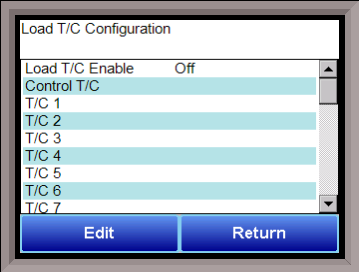
Load T/C Configuration

Configuration of any analog input device must be completed under this menu item. To set the band difference, use the Default Wait Limits menu option. To select one of the load TCs, highlight one of the selections and press the edit button.
Load TC Enable
This value will manually toggle between on, on + alarms, and off.
On – T/C Enabled
On + Alarms – T/C Enabled, Programmer alarm114 provided if out of band (Default wait limits)
Off – T/C not enabled
Control TC
This value allows the user to set the TC to be part of the group of Load TCs that can hold the program if it is out of band. The values are active or not active (shown as blank).
TC 1 – 36
This value allows the user to manually turn the T/C from active to not active, shown as blank, to be part of the group of TCs that can hold the program if it is out of band.
Input 1
This is the control TC.
Input 2
If gauges are used, input 2 may be used for a 10 VDC connection for a gauge. Optionally, input 2 may also be used as a TC input.
Input 3
If gauges are used, input 3 may be used for a 10 VDC connection for a gauge. Optionally, input 3 may also be used as a TC input.
Load T/C Alm Delay (Sec)
This option will allow the user to set a delay time, in seconds, before the load T/C alarm is activated. The range is 0 – 32767.
SP bump maximum step change
SP bump max total change
SP bump change time (sec)
The SP bump feature will adjust the control set point with the goal of bringing all Load TCs into band. It can bump the setpoint higher or lower.
SP bump maximum step change is the maximum interval of degrees the controller will adjust the setpoint.
SP bump max total change is the combined total degrees the controller will adjust the setpoint.
SP bump change time (sec) is the interval of time in seconds between checks to determine if TCs are in band.
NOTE: In order to enable this feature, enter the Zone Assignments option and set the Temp Instrument and Temp Zone Number to “1”
NOTE: The SP bump feature only works if using the GZsoakSB opcode.
SP Bump detailed explanation:
-
The load TC max, min, and average of the active load TC's are determined and stored about once a second.
-
The min and max load TC's are averaged and compared to the original TC setpoint. This difference is the desired bump amount.
-
There is a SP_bump_value register which holds the total amount the SP is bumped. It is set to zero when the GZsoakSB opcode is first entered.
-
The bump change will not exceed the max step change. The bump total change will not exceed the max total change.
-
A value called TC_SP_bump_nxt is updated with the change amount. When the SP bump timer times out, the control TC setpoint is set to the TC_SP_bump_nxt value and the timer is reset.
-
The end result is that the setpoint bump feature will max the average of the min and max load TCs equal to the original target control setpoint.
Minimum Load T/Cs for guarantee
This feature sets a minimum number of Load TCs required to be within band for a guaranteed soak to be evaluated as true. For example, if this value is set to 4, and 6 Load TCs are enabled, the controller will begin counting as soon as 4 Load TCs are within band. If the value is set to 0, this feature is disabled. NOTE: Typically, the Control TC would be disabled to prevent undesired results.
Fail guarantee on active T/C bad coms
This feature prevents the soak timer from running when the instrument cannot communicate with the analog input card connected to the Load TCs. As soon as communications are established and the minimum number of Load TCs (set using the Minimum Load T/Cs for Guarantee feature described above) are within band, the soak timer and guaranteed soak will run.
The Return button will return the user to the menu screen.