Configuration
This option will allow the user to set some general configuration settings.
The list of configurable items is:
-

Log Maintenance -
Programmer Alarm Text
-
Event Text
-
Compact Database
-
Screen
-
Datalogging Setup
-
Recipe Configuration
-
Product Activation
-
Alarm Text
-
Read/Write Data
-
Repair Database
-
Maintenance
-
Time Synchronization
-
Load TC Map
-
Chart Settings
-
Appearance
After configuration changes are made, a shutdown of the 9220 interface is recommended to store or save the settings and changes made.
Log Maintenance
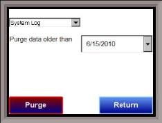
This option will allow the user to purge, or delete, log files, starting from a specific date. All log files from on or before the selected date will be purged. The user can purge log files from the Alarm Log, Event Log, or System Log.

Programmer Alarm Text
This option will allow the user to modify the text for Programmer Alarm 1 – Programmer Alarm 99. Programmer alarms are internal, non-modifiable alarms that are triggered when a recipe that is running uses the Op-Code Alarm. Each alarm is initially labeled by the text “User Alarm #.” However, these labels can be changed to the furnace’s setup. To change the text displayed for an alarm, open the Configurator program, open the Settings, and select the controller to edit. Under Alarm Text, double click any alarm number, enter the new text to be displayed, and hit Ok. User Alarm 0 is not an alarm; it is used to turn off a user alarm. It functions the same way as the acknowledge button.
Event Text
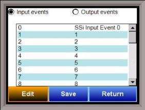
This menu option will allow the user to configure the text for the input and output events for the 9220. Select whether to edit the Input events or the Output Events. Note – The list of events can take a few seconds to load. The screen will refresh after the list has been loaded. There are a total of 31 input events, and 47 output events. Highlight the event to be changed and click on the Edit button. This action will display the on-screen keyboard, which will allow the user to modify the event text. To save the changes to the event text, click on the Save button. Clicking on the Return button will not save any of the changes made. Note: Clicking on the Save button will not close the Edit Event Text screen.
Compact Database
Compacting the database will free up extra space, which will speed up the amount of time it takes the software to communicate with the database. This should be done as needed. Please consult SSi (513-772-0060) for details.
Load TC Map

Load TC Map allows the user to select which Load TCs will be available when using the LTC_SET opcode. Only those TCs selected on this screen will appear as an option when using the opcode. See the description of the LTC_SET opcode in Chapter 4 for more information.
Chart Settings

Chart Settings allows the user to set the default display behavior of the trend chart, specifically in regards to the cursor. See the Chart section for details on the display chart feature.
Screen Communications
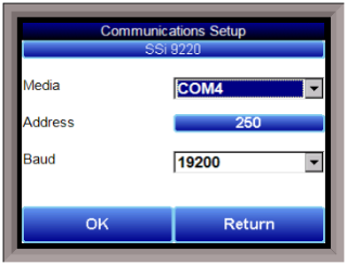
This menu option will allow the user to determine how the Touchscreen will communicate with the 9220 instrument.
The Media option will be the type of connection the Touchscreen is using to connect to the 9220. The options are:
-
COM1
-
COM2
-
COM3
-
COM4
-
Ethernet
If COM1 through COM4 is selected, the user will have to set the Address and the Baud rate as well. If Ethernet is selected, then user will have to enter the IP address of the 9220 instrument.
The Address option is the Client address of the 9220 instrument for the COM port communications, or the Ethernet IP address for Ethernet communications. For the COM port communications, the address will range from 1 to 250. For Ethernet communications, the address must be supplied in a 999.999.999.999 format, or it will not be accepted.
The Baud option is the baud rate for the COM port communications. The options are:
-
1200
-
2400
-
4800
-
9600
-
14400
-
19200
-
28800
-
38400
-
57600
-
76800
-
115200
The button with the number in the bottom left corner of the screen is the timeout time, in milliseconds, of the communications inter-message timeout.
Datalogging Setup

Note – Contact Super Systems before making any changes on this screen, since any changes made can have an adverse effect on the data being displayed.
This menu option will allow the user to modify which registers in the 9220 that the touch screen will datalog.
This list of data values is shown at the top of the screen.
Click on the Add button to add a new set of data values, or click on the Edit button to edit an existing set of data values. Click on the Delete button to delete a set of values. To add or edit data values, enter the initial offset of the register, as well as the number of sequential registers to read for. Clicking on the Save button will save the new data value registers. Note – The Save button must be clicked on to save any changes to the datalog data, including resetting the configuration. Clicking on the Cancel button will cancel the action. Clicking on the Reset button will reset the values to the original configuration. Note: Any changes made to the data values will need a restart of the application before those changes will take effect.
Descriptions can be added only once the new registers are added and saved and the 9220 interface has been shut down and restarted. Clicking on the Descriptions button will display any descriptions for the data values. The default description for a data value is the data value’s register. So the default description for data value 102 is “102”. Changing this to “Temperature”, for example, would make it more descriptive. Register 102 holds the actual temperature value for the 9220. Contact Super Systems for a complete list of 9220 Register Maps.
To add a new description, click on the Add button. To insert a new description, click on the Insert button. To delete a description, click on the Delete button. To edit an existing description, click on the Edit button. The Add or Insert feature will only create valid descriptions if there are existing data values without descriptions. Click on the OK button to save the description changes. Click on the Return button to cancel any changes and return to the previous screen.
Recipe Configuration

By default, recipes are created and stored by a recipe number. The recipe configuration allows a name to be associated with the recipe number. New recipes are still created by recipe number, and must have a name associated with them if the user chooses the option “Recipes on device access by name”. Using this screen, operators can give names to recipes for easy access. The operator must first choose “Recipes on device access by name” from the drop down menu. Next, select the Maintain Recipes button. This screen will allow the operator to Edit and name recipes. Recipes can then be found by name under Recipe Edit.
The Compact Database button will compact the mb.sdf database file that is located on the Touchscreen. When records are added, space is reserved in the database table for the maximum amount of characters, regardless of the actual number of characters in the record. Once the record is added, this space is not released. Instead, it will still be associated with the record, thereby adding to the total disk space and slowing down the communication time with the database. Compacting the database will free up this extra space, which will speed up the amount of time it takes the software to communicate with the database.
Alarm Text
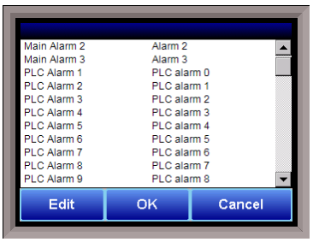
This menu option will allow the user to configure the text for the alarms on the 9220. Main Alarm 1 through Main Alarm 3 are the 3 internal alarms set up in the Alarm Setup menu. The PLC Alarms are alarms used by the PLC. If communications are present between the PLC and the 9220, these alarms can be given text to match the alarms set up in the PLC. Highlight the alarm to be changed and click on the Edit button. This action will display the on-screen keyboard, which will allow the user to modify the alarm text. To save the changes to the alarm text, click on the OK button. Clicking on the Cancel button will not save any of the changes made.
Read/Write Data

This menu option is protected by a special passcode. Contact SSi at 513-772-0060 to obtain this passcode before making any changes.
This menu option is used mainly for technical support reasons. It will read the registers from the 9220 and display those registers on the screen. The user will be able to read from and write to the 9220’s registers. When the screen is first displayed, it will read the first 100 registers from the 9220 and display them in a column format. The top of the list will show “0”, “10”, “20”, etc. These are the column headers. Each value in the column will be a logical increment of the header, where the first value in the column equals the header value. For instance, column “0” will start with register 0, which in the picture has a value of “101”. The next value down is register 1, which has a value of “5”. The next value down is register 2, which has a value of “1”, etc. So, column “40”, 4 values down is register is register 43, which has a value of “9999”.
The number box in the top left of the screen is the beginning register to read from. This will default to 0 when the screen starts. To read registers 100 – 199, edit the value to read “100”. Note – changing the value will automatically begin the read process. This process could take a few seconds to complete.
The “Write offset” value will allow the user to write a specific value listed in the “Write value” box to the register listed in the “Write offset” box. Click on the Write button to write the value to the register. Click on the Return button to return to the Configuration menu. Writing to the register should ONLY be done with the assistance and recommendation of SSi.
Appearance
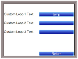
This menu option will allow the user to set custom text for the control loops. The 9220 has only 1 control loop, but will allow you to place text for all 3 analog inputs. To set custom text, select the blue box by the desired loop text you wish to modify. Enter the desired text and press enter.
Time Synchronization

The Time Synchronization menu allows the user to synchronize the time with the 9220 interface with a server setup on the network. This allows the interface’s data to match the time of the data collected on a network server. This also will keep the interface’s time synchronized with the rest of the network. Ethernet communications will have to be setup with the 9220 interface to allow this option to work properly. To enable this option, the Enable checkbox will have to be selected.
In the Blue box that spans the width of the screen, the name of the server will have to be entered. Select the blue box and type in the name of the server.
Maintenance
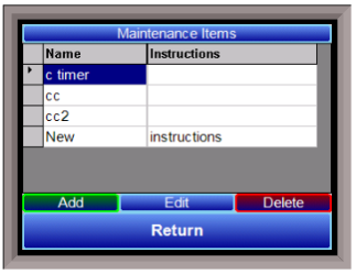
The Maintenance Items option allows the user to set up and edit maintenance events. The Add button will add a new maintenance item.
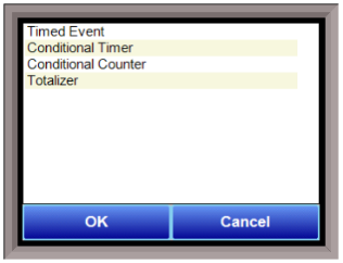
The type of event can be changed by tapping the second blue bar from the top. This will display the options of Timed Event, Conditional Timer, Conditional Counter, and Totalizer. Select the appropriate choice and press OK to add a new event. Cancel will return to the previous screen without adding a new event.
Timed Event

To set up a timed event, the user first selects the interval by tapping on the corresponding blue bar. The choices are Hourly, Daily, Weekly, Monthly, and Yearly. Once the interval is selected, the user then decides how often this interval will be checked.
Conditional Timer
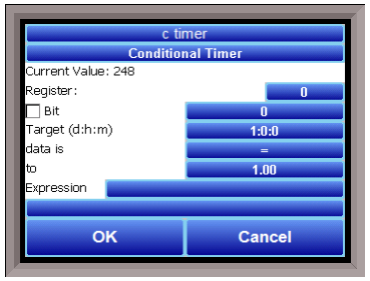
When setting up a conditional timer, the user assigns several parameters. All parameters are changed by tapping on the corresponding blue bar. First the user must assign the Register and/or the Bit. The Bit field does not have to be engaged; the conditional timer can check the entire register instead. The Target determines the amount of time the bit has been on or off until maintenance is needed.
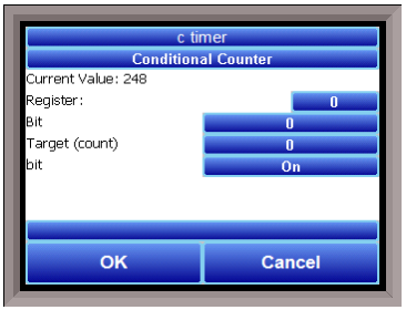
The Conditional Counter counts how many times a bit changes its status. The user assigns the Register, Bit, and Target. Once the Target value is reached, the maintenance item is due. The last field, bit, determines whether the target is counting the bit turning on, the bit turning off, or the bit changing either way.
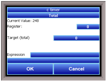
The Totalizer works by checking the assigned Register every minute. Each minute, the current value of the register is added to the total. Once the Target is reached, the item is due for maintenance.
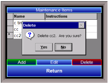
To delete a maintenance item, simply highlight it, and press delete.
Repair Database
This option allows the user to attempt to repair a connected database.