SSi Configuration and Calibration
Overview
The series 9215 can be calibrated using the Instrument Configurator software supplied with the system. Before performing this procedure on a newly installed controller, the unit needs to be powered on for at least 30 minutes for a warm up period.
|
|
The series 9215 has three analog inputs. Each range has a zero and span calibration value. A cold junction trim value must be calibrated for thermocouple inputs. There are two analog outputs each with a zero and span value.
|
Equipment needed
A certified calibrator(s) with the ability to source and read millivolts, milliamps and thermocouples is required. The appropriate connection leads are also required. The operator interface method requires a PC with the Configurator software loaded. An Ethernet crossover cable is required.
Notes
Input 1 – terminals (-) 31 and (+) 32
Input 2 – terminals (-) 29 and (+) 30
Input 3 – terminals (-) 27 and (+) 28
Output 1 – terminals (-) 24 and (+) 25
Output 2 – terminals (-) 25 and (+) 26
Calibrate Aux Analog Input
If an SSi analog input board is set up, then this menu option will be visible. For information on how to calibrate an SSi analog input board, see the Calibrate Aux Analog Input section located at the end of this section.
User Calibration
NOTE: This section details how to calibrate the 9215 inputs. For instructions on calibrating an SSi analog input board, see the Calibrate Aux Analog Input section.
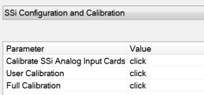
Click on the “click” value next to the “9215 User Calibration” field to start the user calibration. The Calibration screen will be displayed. For complete calibration of Analog Inputs start with step #1, Zero and Span Calibration. The Cold Junction Calibration should be performed AFTER the user has calibrated all of the inputs and, if needed, outputs.
Step 1. Zero then Span Calibration.
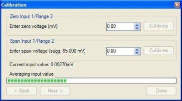
The second screen (Zero/Span Calibration), and all of the subsequent screens, will allow the user to zero and span calibrate the inputs and outputs for the 9215 controller (cold junction calibration will be performed as a final step).
For a zero calibration, a value of 0 mV will need to be sourced to the input or inputs.
In the “Zero Input X/Range Y” section, enter the zero voltage and click on the Calibrate button. This will calibrate the zero range. The progress of the calibration will be shown in the progress bar at the bottom of the screen.
For a span calibration, a value of 90% of the full range (or the adjusted value) will need to be sourced to the input or inputs.
In the “Span Input X/Range Y” section, enter the span voltage that you are sourcing in and click on the Calibrate button. A suggested value will be supplied. This will calibrate the span range. The progress of the calibration will be shown in the progress bar at the bottom of the screen. Repeat these steps for all of the inputs.
Clicking on the Next -> button will display the next screen(s) for the user calibration. Clicking on the
<- Back button will display the previous screen(s).
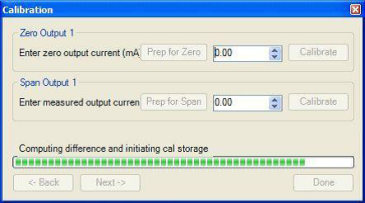
To calibrate the zero range for the outputs, you must first attach your measuring device.
In the “Zero Output X” section, click on the Prep for Zero button. Let the unit output what it has set for the zero measurement, then enter what you are measuring coming out of the terminals. Once entered, click on the Calibrate button and let the procedure finish. The progress of the calibration will be shown in the progress bar at the bottom of the screen.
In the “Span Output X” section, click on the Prep for Span button. Let the unit output what it has set for the span measurement, then enter what you are measuring coming out of the terminals. Once entered, click on the Calibrate button and let the procedure finish. The progress of the calibration will be shown in the progress bar at the bottom of the screen. Repeat these steps for all of the outputs.
Once all of the inputs and outputs have been calibrated, return to the first screen for cold junction calibration, if necessary.
Step 2. Cold Junction Calibration.
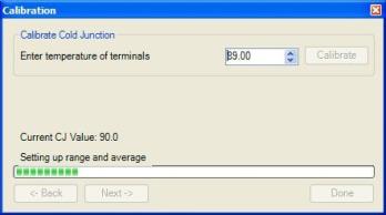
NOTE: Perform zero and span calibrations (see previous section) before following this procedure.
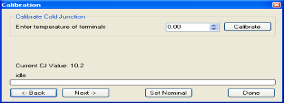
The “Cold Junction” option will allow the user to perform a cold junction trim on the 9215 analog input board.
To determine if a cold junction adjustment is needed, hook up the calibrator with the appropriate T/C wire attached (reference the specific input under the “Analog Input Setup” menu), then source a temperature to the input. It is best to use an operating temperature to source; for example, if the furnace typically runs at 1700 °F, then 1700 °F should be sourced to the input. Source a range of temperatures – this will help determine whether any difference in readings is linear.
NOTE: This value is NOT the temperature displayed on the “Cold Junction Calibration” menu option – rather, this is the value displayed on the main screen along with set point and output.
If the displayed value does not equal the value being sourced, then a Cold Junction Calibration may be necessary. To begin, note the difference between the displayed temperature and the sourced temperature. This is the adjustment that will be made in the “Cold Junction” menu. For example:
|
Source Temp |
Displayed Temp |
Difference |
Cold Junction Adjustment |
Current Temp of Terminals |
New Temp of Terminals |
|
1700 |
1711 |
11 High |
-11 |
72 |
61 |
In this situation, the displayed temperature on the main screen is 11° higher than the sourced input. Therefore, 11° must be subtracted from the current “temperature of terminals” reading. Use the up and down arrows to adjust the “Enter temperature of terminals” input box to the appropriate value (in this case, 61).
Click on the “Calibrate” button to begin the calibration.
After 30 minutes, verify the calibration by again sourcing a temperature to the input and checking the displayed temperature reading on the main display. It is recommended to perform this calibration check after every cold junction calibration.
Click on the Done button to close down the screen.
Full Calibration
NOTE: Full calibration is performed by SSi. The below information is provided for reference only.
The Calibration screen for the Full Calibration menu option is identical in function and layout to the User Calibration’s Calibration screen. The only difference is the Full Calibration’s Calibration screen contains more screens. This list of screens is listed below in sequential order. Screens only found in the Full Calibration menu option are displayed in Italics. Screens only found in the User Calibration menu option are displayed in bold.
-
Cold Junction
-
Zero/Span Input 0/Range 0
-
Zero/Span Input 0/Range 1
-
Zero/Span Input 0/Range 2
-
Zero/Span Input 0/Range 3
-
Zero/Span Input 1/Range 0
-
Zero/Span Input 1/Range 1
-
Zero/Span Input 1/Range 2
-
Zero/Span Input 1/Range 3
-
Zero/Span Input 2/Range 0
-
Zero/Span Input 2/Range 1
-
Zero/Span Input 2/Range 2
-
Zero/Span Input 2/Range 3
-
Zero/Span Input 3/Range 2
-
Zero/Span Input 1 Range Jumper
-
Zero/Span Input 2 Range Jumper
-
Zero/Span Input 3 Range Jumper
-
Zero/Span Output 1
-
Zero/Span Output 2
The Calibration screen for the Full Calibration menu option also has a Set Nominal button, which will set nominal values for the current screen. The user will have to confirm the action.

Clicking on the Yes button will set the nominal values, and clicking on the No button will cancel the action.
Click the Done button to close the screen down.
Calibrate Aux Analog Input
NOTE: This section details how to calibrate an SSi analog input board, not the 9215 inputs themselves. For instructions on calibrating the 9215 inputs through configurator, see the User Calibration section.
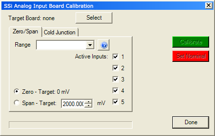
If an SSi analog input board is applicable, then this menu option will be visible. The Calibration menu screen will allow the user to calibrate the zero, span, and cold junction trim value for all of the inputs on each board.
The Select button will allow the user to select one of the current boards to calibrate.
Select the appropriate board and click on the OK button. Clicking on the Cancel button will not select the board to calibrate. Note: A board must be selected for calibration to begin.
The user will need a thermocouple calibrator capable of sourcing a thermocouple signal to calibrate the zero, span or cold junction value. It is recommended to let everything (calibrator and datalogger) sit for approximately thirty minutes to allow the temperature to achieve equilibrium. Set up the calibrator for the specific thermocouple type, i.e. type K, type J, etc. Then, source a specific temperature, like 1000°F, or millivolt to the connected input. It is recommended that the actual temperature used be similar to an appropriate process temperature. For example, if your equipment normally operates at 1700°F, then perform the cold junction calibration using a 1700 °F signal. It is important to note that when performing a zero or span calibration, do not use regular thermocouple wiring. Instead, use any kind of regular sensor wire, or even regular copper wire. To perform the calibrations, the user will need a calibrator that is capable of outputting volts, millivolts, and temperature.
The “Zero/Span” tab will allow the user to perform a zero and span calibration on the selected board.
The help button -  - next to the “Range” drop-down list will allow the user to select a range based upon an input type if the range is not known.
Select the input type and click on the OK button. The correct millivolt range will be displayed in the drop-down list. Click on the Cancel button to cancel this action.
Below is a listing of the suggested ranges for the various TC types.
