Appendix 4 – Calibration of SSi Analog Input Boards

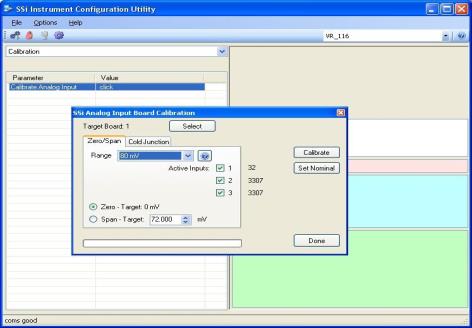
The Calibration menu screen will allow the user to calibration the zero, span, and cold junction trim value for all of the inputs on each board.
The Select button will allow the user to select one of the current boards to perform a calibration on.
Select the appropriate board and click on the OK button. Clicking on the Cancel button will not select the board to calibrate. Note: A board must be selected for calibration to begin.


The user will need a thermocouple calibrator capable of outputting a thermocouple signal to calibrate the zero, span or cold junction value of the video recorder data logger. The user will need to connect the calibrator to one of the inputs on the data logger for the channel that will be calibrated. It is recommended to let everything (calibrator and datalogger) sit for approximately thirty minutes to allow the temperature to achieve equilibrium. Set up the calibrator for the specific thermocouple type of the thermocouples in the video recorder datalogger, i.e. type K, type J, etc. Then, source a specific temperature, like 1000 °°°do not use regular thermocouple wiring. Instead, use any kind of regular sensor wire, or even regular copper wire. To perform the calibrations, the user will need a calibrator that is capable of outputting volts, millivolts, and temperature.
The “Zero/Span” tab will allow the user to perform a zero and span calibration on the selected board.
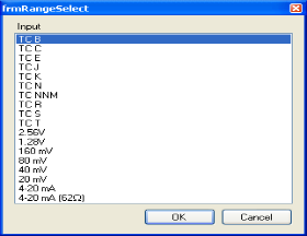
The help button -  - next to the “Range” drop-down list will allow the user to select a range based upon an input type if the range is not known.
Select the input type and click on the OK button. The correct millivolt range will be displayed in the drop-down list. Click on the Cancel button to cancel this action.
Below is a listing of the suggested ranges for the various TC types.
TC Type mV Range Chart
| TC Type | Range in mV |
| B | 20 |
| C | 40 |
| E | 80 |
| J | 80 |
| K | 80 |
| N | 80 |
| NNM | 80 |
| R | 40 |
| S | 20 |
| T | 20 |
Zero Calibration
To perform a zero calibration, click on the “Zero” option. The circle will be filled in for the selected option. The drop down list under “Range” will allow the user to select the millivolt range of the inputs being calibrated. When a range is selected, the recommended value will also be populated. For a zero calibration, the recommended value is 0. The list of ranges is:
20 mV
40 mV
80 mV
160 mV
1.28 Volt
The user can individually select each input (one through three/five) to calibrate, where Check = yes (calibrate) and No Check = no (do not calibrate). Once an input is checked, its current value will be displayed.
For a zero calibration, a value of 0 mV will need to be sourced to the input or inputs.
Click on the Calibrate button to begin the calibration.
The Set Nominal button will set all calibration values to their theoretical values. Note: This function is not a factory default calibration. This function would be useful if the user wished to restart a calibration from scratch.
A progress bar will be displayed along the bottom of the screen giving the progress of the calibration.
Span Calibration
To perform a span calibration, click on the “Span” option. The circle will be filled in for the selected option. The drop down list under “Range” will allow the user to select the millivolt range of the inputs being calibrated. When a range is selected, the recommended value will also be populated. For a span calibration, the recommended value is 90 % of the full range. For example, if the range is 80 mV, then the span should be 72. The recommended value can be changed either by using the up and down arrows to adjust the value, or by clicking on the value, and entering the new value that way. The user can also individually select each input (one through five) to calibrate, where Check = yes (calibrate) and No Check = no (do not calibrate). Once an input is checked, its current value will be displayed.
For a span calibration, a value of 90 % of the full range will need to be sourced to the input or inputs.
Click on the Calibrate button to begin the calibration.
The Set Nominal button will set all calibration values to their theoretical values. Note: This function is not a factory default calibration. This function would be useful if the user wished to restart a calibration from scratch.
A progress bar will be displayed along the bottom of the screen giving the progress of the calibration.
Cold Junction Calibration
The “Cold Junction” tab will allow the user to perform a cold junction trim on the selected board.
The user can select the input to perform the trim on from the “Input:” box. The user can enter the cold junction offset in the “Offset:” box. The current cold junction value will be displayed next to the “CJ:” line. Also, the current values from the selected inputs will be displayed on the right of the tab. To display an input’s value on the “Cold Junction” tab, click on the “Zero/Span” tab and check that input’s checkbox, then return to the “Cold Junction” tab. Click on the Calibrate button to begin the calibration.
Click on the Done button to close down the screen.