User Calibration
*** Calibrate the inputs first, then perform a cold junction calibration ***
The user will need a thermocouple calibrator capable of outputting a thermocouple signal to calibrate the zero, span or cold junction value of the 9210 instrument. The user will need to connect the calibrator to one of the inputs on the instrument that will be calibrated. It is recommended to let everything (calibrator and instrument) sit for approximately thirty minutes to allow the temperature to achieve equilibrium. Set up the calibrator for the specific thermocouple type of the thermocouples in the 9210 instrument, i.e. type K, type J, etc. Then, source a specific temperature, like 1000 °F, or millivolt to the connected input. It is recommended that the actual temperature used be similar to an appropriate process temperature. For example, if your equipment normally operates at 1700 °F, then perform the cold junction calibration using a 1700 °F signal. It is important to note that when performing a zero or span calibration, do not use regular thermocouple wiring. Instead, use any kind of regular sensor wire, or even regular copper wire. To perform the calibrations, the user will need a calibrator that is capable of outputting volts, millivolts, and temperature.
Note: The buttons on the screen always have the same functionality. The ßBack button will display the previous screen, if any. The Skip button will skip the current screen and display the next screen, if any. The Next ® button will display the next screen, if any. The Done button will close out the User Calibration menu. The Edit button will display a numeric keypad from which the user can enter a new value for the calibration process. The Calibrate button will begin the calibration process for the selected screen.
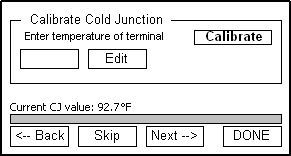
The first screen in the User Calibration menu is the Calibrate Cold Junction screen. This will allow the user to enter an offset for the cold junction value. The current value is displayed directly above the progress bar and bottom row of buttons as “Current CJ value: XX.X ° F”. Press the Calibrate button to set the cold junction offset. The progress bar at the bottom of the screen will display the calibration progress. NOTE: This function should be performed AFTER the inputs have been calibrated.
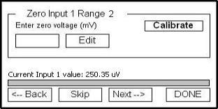
The next screen is the Zero Input 1 Range 2 screen. This screen will allow the user to set the zero scale for Input 1 Range 2. A value of 0 millivolts will need to be sourced to the inputs. For a zero calibration, enter a 0 as the value of the terminal to correctly calibrate the inputs. The current Input 1 value will be displayed near the bottom of the screen as “Current Input 1 value: xxxx.xx uV”. The progress bar at the bottom of the screen will display the calibration progress.
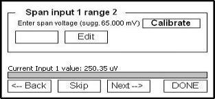
The next screen is the Span Input 1 Range 2 screen. This screen will allow the user to set the span value for Input 1 Range 2. A suggested value will be displayed next to the Calibrate button (“sugg. 65.000 mV”). The current Input 1 value will be displayed near the bottom of the screen as “Current Input 1 value: xxxx.xx uV”. The progress bar at the bottom of the screen will display the calibration progress.
The next screen is the Zero Input 2 Range 0 screen. This screen will allow the user to set the zero scale for Input 2 Range 0. A value of 0 millivolts will need to be sourced to the inputs. For a zero calibration, enter a 0 as the value of the terminal to correctly calibrate the inputs. The current Input 2 value will be displayed near the bottom of the screen as “Current Input 2 value: xxxx.xx uV”. The progress bar at the bottom of the screen will display the calibration progress.
This process can be repeated for the rest of the inputs.
*** Once the inputs have been calibrated, go back to the first screen and perform a cold junction calibration ***
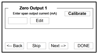
The next screen is the Zero Output 1 screen. This screen will allow the user to set the zero value for Output 1. Measured at terminals 24(-) and 25(+) for this step. The progress bar at the bottom of the screen will display the calibration progress.
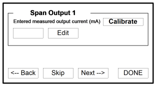
The next screen is the Span Output 1 screen. This screen will allow the user to set the span value for Output 1. Measured at terminals 24(-) and 25(+) for this step. The progress bar at the bottom of the screen will display the calibration progress. This process can be repeated for the rest of the outputs.
The next screen indicates that the calibration process is complete.