Configuration
Recipe Configuration
This option will allow the user to set some general configuration settings.
The list of configurable items is:
-
Log Maintenance
-
Programmer Alarm Text
-
Event Text
-
Compact Database
-
Communications Setup
-
Datalogging Setup
-
Product Activation
-
Alarm Text
-
Load TC Map
-
Chart Settings
-
Read/Write Data
Log Maintenance
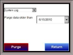
This option will allow the user to purge, or delete, log files, starting from a specific date. All log files from on or before the selected date will be purged. The user can purge log files from the Alarm Log, Event Log, or System Log.
Programmer Alarm Text
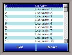
This option will allow the user to modify the text for Programmer Alarm 1 – Programmer Alarm 99. Programmer alarms are internal, non-modifiable alarms that are triggered when there is a certain condition in the 9130 programmer. Each alarm is initially labeled by the text “User Alarm #.” However, these labels can be changed to the operator’s preference. To change the text displayed for an alarm, open the Configurator program, open the Settings, and select the controller to edit. Under Alarm Text, double click any alarm number, enter the new text to be displayed, and hit Ok. User Alarm 0 is not an alarm; it is used to turn off a user alarm. It functions the same way as the acknowledge button.
Event Text
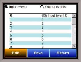
This menu option will allow the user to configure the text for the input and output events for the 9130. Select whether to edit the Input events or the Output Events. Note – The list of events can take a few seconds to load. The screen will refresh after the list has been loaded. There are a total of 31 input events, and 47 output events. Highlight the event to be changed and click on the Edit button. This action will display the on-screen keyboard, which will allow the user to modify the event text. To save the changes to the event text, click on the Save button. Clicking on the Return button will not save any of the changes made. Note – Clicking on the Save button will not close the Edit Event Text screen.
Compact Database
This menu option will automatically compact the DW9130DB.sdf database. This database will keep track of all of the alarms, events, recipes, and system events that occur on the 9130. When records are added, space is reserved in the database table for the maximum amount of characters, regardless of the actual number of characters in the record. Once the record is added, this space is not released. Instead, it will still be associated with the record, thereby adding to the total disk space and slowing down the communication time with the database. Compacting the database will free up this extra space, which will speed up the amount of time it takes the software to communicate with the database.
Communications Setup
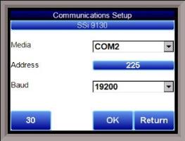
This menu option will allow the user to determine how the Touchscreen will communicate with the 9130 instrument.
The Media option will be the type of connection the Touchscreen is using to connect to the 9130. The options are:
-
COM1
-
COM2
-
COM3
-
COM4
-
Ethernet
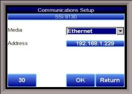
If COM1 through COM4 is selected, the user will have to set the Address and the Baud rate as well. If Ethernet is selected, then user will have to enter the IP address of the 9130 instrument.
The Address option is the Client address of the 9130 instrument for the COM port communications, or the Ethernet IP address for Ethernet communications. For the COM port communications, the address will range from 1 to 250. For Ethernet communications, the address must be supplied in a 999.999.999.999 format, or it will not be accepted.
The Baud option is the baud rate for the COM port communications. The options are:
-
1200
-
2400
-
4800
-
9600
-
14400
-
19200 -
28800
-
38400
-
57600
-
76800
-
115200
The button with the number in the bottom left corner of the screen is the timeout time, in milliseconds, of the communications intermessage timeout.
Datalogging Setup
Note – Contact Super Systems before making any changes on this screen, since any changes made can have an adverse effect on the data being displayed.
This menu option will allow the user to modify which registers in the 9130 will be used as datalog data.
This list of data values is shown at the top of the screen.
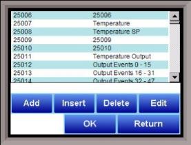
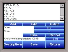
Click on the Add button to add a new set of data values, or click on the Edit button to edit an existing set of data values. Click on the Delete button to delete a set of values. To add or edit data values, enter the initial offset of the register, as well as the number of sequential registers to read for. Using the example from the image, the data values added would be: 850, 851, 852, 853, and 854. Clicking on the Save button will save the new data value registers. Note – The Save button must be clicked on to save any changes to the datalog data, including resetting the configuration. Clicking on the Cancel button will cancel the action. Clicking on the Reset button will reset the values to the original configuration. Note – any changes made to the data values will need a restart of the application before those changes will take effect. Clicking on the Descriptions button will display any descriptions for the data values. The default description for a data value is the data value’s register. So the default description for data value 25007 is “25007”. Changing this to “Temperature”, for example, would make it more descriptive. Register 25007 holds the actual temperature value for the 9130.
To add a new description, click on the Add button. To insert a new description, click on the Insert button. To delete a description, click on the Delete button. To edit an existing description, click on the Edit button. The Add or Insert feature will only create valid descriptions if there are existing data values without descriptions. Click on the OK button to save the description changes. Click on the Return button to cancel any changes and return to the previous screen.
Recipe Configuration
This menu option is not currently available on the 9130.
The Compact Database button will compact the mb.sdf database file that is located on the Touchscreen. When records are added, space is reserved in the database table for the maximum amount of characters, regardless of the actual number of characters in the record. Once the record is added, this space is not released. Instead, it will still be associated with the record, thereby adding to the total disk space and slowing down the communication time with the database. Compacting the database will free up this extra space, which will speed up the amount of time it takes the software to communicate with the database.
Product Activation
This menu option is not currently available on the 9130.
Alarm Text
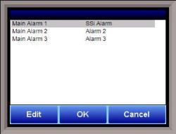
This menu option will allow the user to configure the text for the three main alarms on the 9130. Highlight the alarm to be changed and click on the Edit button. This action will display the on-screen keyboard, which will allow the user to modify the alarm text. To save the changes to the alarm text, click on the OK button. Clicking on the Cancel button will not save any of the changes made.
Load TC Map

Load TC Map allows the user to select which Load TCs will be available when using the LTC_SET opcode. Only those TCs selected on this screen will appear as an option when using the opcode. See the description of the LTC_SET opcode in Chapter 4 for more information.
Chart Settings

Chart Settings allows the user to set the default display behavior of the trend chart, specifically in regards to the cursor. See the Chart section for details on the display chart feature.
Read/Write Data
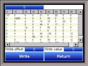
This menu option is protected by the SSi special passcode. Contact SSi at 513-772-0060 to obtain this passcode before making any changes.
This menu option is used mainly for technical support reasons. It will read the registers from the 9130 and display those registers on the screen. The user will be able to read from and write to the 9130’s registers. When the screen is first displayed, it will read the first 100 registers from the 9130 and display them in a column format. The top of the list will show “0”, “10”, “20”, etc. These are the column headers. Each value in the column will be a logical increment of the header, where the first value in the column equals the header value. For instance, column “0” will start with register 0, which in the picture has a value of “101”. The next value down is register 1, which has a value of “5”. The next value down is register 2, which has a value of “1”, etc. So, column “40”, 4 values down is register is register 43, which has a value of “9999”.
The number box in the top left of the screen is the beginning register to read from. This will default to 0 when the screen starts. To read registers 100 – 199, edit the value to read “100”. Note – changing the value will automatically begin the read process. This process could take a few seconds to complete.
The “Write offset” value will allow the user to write a specific value listed in the “Write value” box to the register listed in the “Write offset” box. Click on the Write button to write the value to the register. Click on the Return button to return to the Configuration menu.