Aux Analog Input Setup

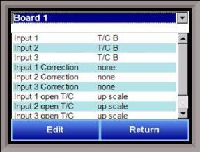
The Auxiliary Analog Input Setup menu option allows the user an input selection of three inputs per board, three input corrections per board, and three input open T/Cs per board. There are eight (8) boards available. It is configurable for voltage of T/C (universal input), and it is typically used for Load T/Cs and Auxiliary Flow Meters.
Input 1 – Input 3
This will select the input types for the board. The options are:
B
C
E
J
K
N
NNM
R
S
T
2.5 volts
1.25 volts
160 mV
80 mV
40 mV
20 mV
4-20 mA/124W
4-20 mA/62W
Input 1 Correction – Input 3 Correction
This option will set a correction curve for the input. The options for the input corrections are: not used, Curve 1 – Curve 3.
Input 1 Open T/C – Input 3 Open T/C
This option will allow the user to set the direction of the open T/C for each input. The options are: Up Scale or Down Scale.
Calibration
This option will allow the user to calibrate the auxiliary input board once the settings have been confirmed.
Equipment needed
A certified calibrator(s) with the ability to input and read millivolts, milliamps and thermocouples is required. The appropriate connection leads are also required. A 24VDC 75-watt power supply is required.
To calibrate an auxiliary input, select the “Cold Junction” option or the “Zero/Span” option. Note – Even though the “Cold Junction” option is listed first, the inputs and outputs should have the zero and span calibration performed BEFORE performing a cold junction calibration. No calibration can be performed from the initial screen that is displayed when the “Calibration” menu option is selected.
Zero Calibration
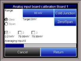
To perform a zero calibration, click on the “Zero” option - The circle will be filled in with a dot for the selected option. The millivolt range for the input will need to be set so that the span values are correct. The chart below will determine the range for each T/C type.
TC Type mV Range Chart
TC Type Range in mV

B 20
C 40
E 80
J 80
K 80
N 80
NNM 80
R 40
S 20
T 20
For a zero calibration, the recommended value to source is 0 mV. The user can also individually select each input (one through three/five) to calibrate, where Check = yes (calibrate) and No Check = no (do not calibrate).
Click on the Calibrate button to begin the calibration.
A progress bar will be displayed along the bottom of the screen giving the progress of the calibration.
Span Calibration

To perform a span calibration, click on the “Span” option - The circle will be filled in with a dot for the selected option. The millivolt range for the input will need to be set so that the span values are correct. When a range is selected, the recommended value will also be populated. For a span calibration, the recommended value is 90 % of the full range. For example, if the range is 80 mV, then the span should be 72 mV. The recommended value can be changed by clicking on the recommended value and entering the new value. The user can also individually select each input (one through three/five) to calibrate, where Check = yes (calibrate) and No Check = no (do not calibrate). Once an input is checked, its current value will be displayed.
For a span calibration, a value of 90 % of the full range (or the adjusted value) will need to be sourced to the input or inputs.
Click on the Calibrate button to begin the calibration.
A progress bar will be displayed along the bottom of the screen giving the progress of the calibration.
Cold Junction Calibration
The “Cold Junction” option will allow the user to perform a cold junction trim on the selected board.
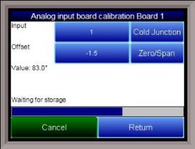
The user can select the input to perform the trim on from the “Input” box. The user can enter the cold junction offset in the “Offset” box. The current temperature value will be displayed next to the “Value:” line.
To determine if a cold junction adjustment is needed, hook up the calibrator with the appropriate T/C wire attached, and source a temperature to the input. It is recommended to use an operating temperature to source. For example, if the furnace typically runs at 1700 °F, then 1700 °F should be sourced to the input. If the displayed value does not equal the value being sourced, then a cold junction adjust would be necessary. The “Offset” will be the amount of change desired. For example, if 1700°F is being sourced, and the “Value” is showing 1696.4 °F, then the “Offset” would be set to 3.6. If 1700 °F is being sourced, and the “Value” is showing 1702.3 °F, then the “Offset” would be set to -2.3.
Click on the Calibrate button to begin the calibration.
Wait 120 seconds and verify with a source calibration device with the correct T/C type. Note: During a normal calibration procedure, the user should zero and span all of the inputs first and then perform a cold junction calibration, if necessary.
It is recommended after each Cold Junction calibration to source a value in and check what the displayed temperature reading is.
Click on the Return button to return to the main menu screen.