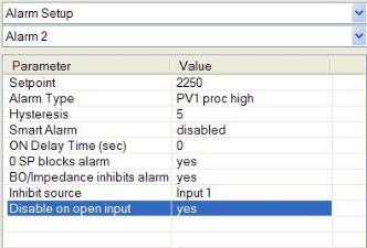
Alarm Setup

The 9130 controller can be configured to use three (3) different alarms, and a Thermocouple Check. Each of the alarms consists of an alarm setpoint, alarm type, alarm hysteresis, smart alarm, ON delay time, 0 SP blocks alarm value, Burnoff/Impedance inhibits alarm, Inhibit source, and disable on open input. The alarms come from the factory with a default configuration dependent on the application but also can be modified prior to shipment to your facility or in the field by a supervisor.
Setpoint
This value is the setpoint for the alarm. Clicking on this value will display an input box from which the user can select a new value. The range is from –9999 to 9999.
Alarm Type
This value is the type of alarms used. Clicking on this value will display an input box with two (2) drop-down lists from which the user can select a new value.
The values in the first (top) list box are:
PV 1 Value
PV 2 Value
N/A
Input 1 Value
Input 2 Value
Input 3 Value
PO1 Value
PO2 Value
N/A
The values in the second (bottom) list box are:
Process High
Process Low
Out of Band
In Band
Outside Deviation
Within Deviation
Hysteresis
This value is the Hysteresis value. The Hysteresis is a set number that works with the alarm to help control a motor or pump longer to reach a set amount to come back into band before it will shut off motor or pump.
Example: Using quench oil as an example, suppose the SP is 200 °F. The alarm is set as a deviation of +10 °F. At 210 °F, the alarm is active and the pump will run to cool the oil. With a hysteresis of 8 °F, the alarm and pump will turn off at 202 °F. It will turn back on when it is 10 °F above setpoint. If the setpoint is still 200 °F, then at 210 °F, it will turn on again.
Clicking on this value will display an input box from which the user can select a new value. The range is from 0 to 9999.
Smart Alarm
This value is a display of the Smart Alarm status. A smart alarm is an alarm that works with a Process Variable (PV), and, when enabled, it will not be active until the PV is within band of the setpoint. The alarm sounding - if active - will be disabled until within the SP band. When it is in band, the alarm will go active unless on delay time is set.
Example: If the SP is 1700 °F and the band is 10 °F, the alarm will not be active until the PV reaches 1690 °F. The value can be either disabled or enabled.
ON Delay Time
This value is the ON Delay Time. Clicking on this value will display an input box from which the user can select a new value. The range is from 0 to 9999.
0 SP Blocks Alarm
This value will allow a 0 setpoint to block an alarm. The options are either no or yes.
Bo/Impedance Inhibits Alarm
This option will allow the user to specify if a burnoff or impedance test will keep the alarm from sounding. The options are either no or yes.
Inhibit Source
This option will allow the user to set the source of the inhibit signal. The options are: None, Input 1 – Input 4, Soak Timer Inactive, Input 6 – Input 15.
Disable on Open Input
This option will allow the user to specify if the alarm is disabled when the input is open. The options are either no or yes.