Generic Instrument Setup

The generic instrument’s data will be stored in certain registers on the host instrument, such as the 9125 controller. Each instrument is allotted a certain set of registers, starting with register 1000. To determine the beginning register, use the following calculation: (100 * generic instrument’s number (1 – 16)) + 900. Therefore, instrument 1 would begin at register 1000: (100 * 1) + 900. Instrument 7 would begin at register 1600: (100 * 7) + 900. Each instrument is allotted 100 registers, therefore, instrument 1’s allotment is from register 1000 to 1099 on the 9125 controller, instrument 2’s allotment is from register 1100 to 1199 on the 9125 controller, etc.
The Generic Instrument Setups menu is split into two parts: Coms, and Data. The screen lists the generic instruments from Instrument 1 to Instrument 16. Select the desired instrument to configure, then choose Coms or Data.
Coms
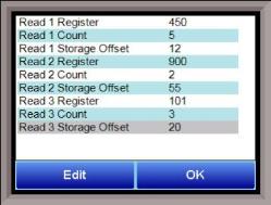
The three reads can be set up on this screen.
Read 1 Register, Read 2 Register, Read 3 Register
The Read X Register field will be the register in the 9125 controller that the instrument will read from. The range is 0 – 32767.
Read 1 Count, Read 2 Count, Read 3 Count
The Read X Count field will be the number of successive registers to read. The range is 0 – 100.
Read 1 Storage Offset, Read 2 Storage Offset, Read 3 Storage Offset
The Read X Storage Offset field will be the offset in the generic instruments registers (1000 – 1099 for Instrument 1, 1100 to 1199 for Instrument 2, etc). The range is 0 – 100.
Data

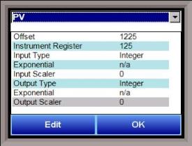
The Process Variable (PV), Setpoint (SP), and Output (Out) can be set up from this screen. Select the desired option from the drop-down list to configure those settings.
Offset
The Offset field is the instrument’s register offset. The range is 0 – 32767.
Instrument Register
The Instrument Register field is the register in the 9125 controller. The range is 0 – 32767.
Input Type
The Input Type field will determine what kind of type the value will be. The options are: Integer, Big Endian, Big Endian Byte Swap, Little Endian, or Little Endian Byte Swap.
Exponential
The Exponential field will determine if there is an exponent value. For “Integer” Input Types, exponents do not apply, so this field is not modifiable. If the Input Type is not “Integer”, the options for the exponential are: Yes or No. This will cause the Scaler to be a power of 10.
Input Scaler
The Input Scaler field will determine the input scaler range. The Scaler is a power of ten in the range -30 to +30.
Output Type
The Output Type will determine what kind of the output value will be. The options are: Integer, Big Endian, Big Endian Byte Swap, Little Endian, or Little Endian Byte Swap.
Exponential
The Exponential field will determine if there is an exponent value. For “Integer” Input Types, exponents do not apply, so this field is not modifiable. If the Input Type is not “Integer”, the options for the exponential are: Yes or No. This will cause the Scaler to be a power of 10.
Output Scaler
The Output Scaler field will determine the Output Scaler range. The Scaler is a power of ten in the range -31 to +31.