User Calibration
Click on the “click” value next to the “9125 User Calibration” field to start the user calibration. The Calibration screen will be displayed. For complete calibration of Analog Inputs start with step #1, Zero and Span Calibration. The Cold Junction Calibration should be performed AFTER the user has calibrated all of the inputs and, if needed, outputs.
Step 1. Zero then Span Calibration.

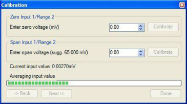
The second screen (Zero/Span Calibration), and all of the subsequent screens, will allow the user to zero and span calibrate the inputs and outputs for the 9125 controller (cold junction calibration will be performed as a final step).
For a zero calibration, a value of 0 mV will need to be sourced to the input or inputs.
In the “Zero Input X/Range Y” section, enter the zero voltage and click on the Calibrate button. This will calibrate the zero range. The progress of the calibration will be shown in the progress bar at the bottom of the screen.
For a span calibration, a value of 90% of the full range (or the adjusted value) will need to be sourced to the input or inputs.
In the “Span Input X/Range Y” section, enter the span voltage that you are sourcing in and click on the Calibrate button. A suggested value will be supplied. This will calibrate the span range. The progress of the calibration will be shown in the progress bar at the bottom of the screen. Repeat these steps for all of the inputs.
Clicking on the Next -> button will display the next screen(s) for the user calibration. Clicking on the
<- Back button will display the previous screen(s).

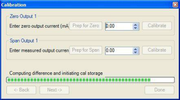
To calibrate the zero range for the outputs, you must first attach your measuring device.
In the “Zero Output X” section, click on the Prep for Zero button. Let the unit output what it has set for the zero measurement, then enter what you are measuring coming out of the terminals. Once entered, click on the Calibrate button and let the procedure finish. The progress of the calibration will be shown in the progress bar at the bottom of the screen.
In the “Span Output X” section, click on the Prep for Span button. Let the unit output what it has set for the span measurement, then enter what you are measuring coming out of the terminals. Once entered, click on the Calibrate button and let the procedure finish. The progress of the calibration will be shown in the progress bar at the bottom of the screen. Repeat these steps for all of the outputs.
Once all of the inputs and outputs have been calibrated, return to the first screen for cold junction calibration, if necessary.
Step 2. Cold Junction Calibration.
If you have recently finished the zero and span calibration, and the calibration screen is still displayed, select “Done” and return to the user display. Set up the calibrator for the specific thermocouple type of the thermocouples in the analog board: type K, type J, etc. Then source a specific temperature, like 1000°F. It is recommended that the actual temperature used be similar to an appropriate process temperature. For example, if your equipment normally operates at 1700°F, then perform the cold junction calibration using a 1700°F signal. Compare what you source (on meter) to what the actual reading is (shown in Configurator). If the values are out of tolerance (per your specifications), then refer back to the User Calibration section.

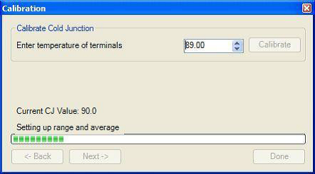
The user can enter the cold junction offset in the box next to the Calibrate button. The current cold junction value will be displayed next to the “Current CJ Value:” line.
To determine whether a cold junction adjustment is necessary, source a specific temperature to the input (as explained above). If the temperature reading displayed is not sufficiently close to the source value, then the “Offset” will need to be changed. Enter the amount of change in the “Temperature of Terminals” box. If the input was showing 1748°F, while sourcing 1750°F, then the “Offset” difference would be 2°F to bring the display back up to 1750°F.
Note: The current cold junction value is for display purposes. It will need to be used when determining the cold junction offset. You will need to add to or subtract from the displayed value the amount of difference, example 2°F difference being applied to 90 (like in the image) your new CJ value will need to be 92°F.
When ready click on the Calibrate button to begin the calibration.
Wait 120 seconds and verify with a source calibration device with the correct T/C type. Note: During a normal calibration procedure, the user should zero and span calibrate all of the inputs first and then perform a cold junction calibration, if necessary.
Click on the Done button when finished. You will then be able to verify on the main display your sourced value when compared to the actual reading in Configurator.