Section 3 – 9120 Web Pages
The 9120 controller has a simple website that will display some of the information associated with the 9120, including current PV values and setpoints, among others. The website can be accessed by any computer that is on the same network as the 9120 – directly through a crossover Ethernet cable, or on a local company network. To access the website, just type in the IP address of the controller, not the Touchscreen, into an web browser’s address bar:

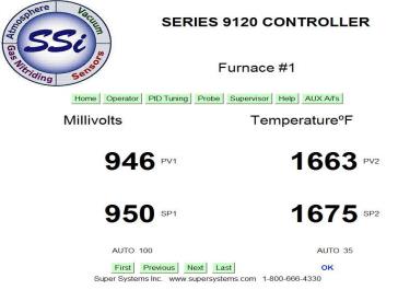
The main page will be displayed, which will display the PVT values as well as the current setpoints. The name of the furnace (from Furnace Setup menu) will be listed as well. The buttons across the top and bottom of the screen will allow interaction with the specific item on the 9120. No modifications can be made from the main screen.
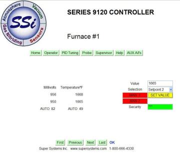
The Operator button will allow the user to modify the PV setpoints, as well as the manual % on the PV. To make any changes, the user will have to enter the supervisor or administrator web passwords first (Furnace Setup menu). Once the password has been entered, select the option to modify – Setpoint 1, Setpoint 2, Output Pwr 1 (PV 1 control percent output), or Output Pwr 2 (PV 2 control percent output) – and enter the value in the “Value” box. Note – The security box will turn green when the Set Value button is pressed and the password is correct. If it is not correct, the box will stay red. The Output Pwr 1 and Output Pwr 2 options can only be modified when the furnace PV is set to Manual. To set the PV to manual, click on the MAN 1 button for PV 1, or click on MAN 2 button for PV 2. Once the change has been made, the buttons will change to AUTO 1 or AUTO 2, as well as change color from red to green. The changes may take a few seconds to be updated on the screen.
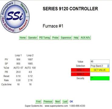
The PID Tuning button will allow the user to modify the PV setpoints, the manual % on the PV, as well as the PID parameters for both loops. To make any changes, the user will have to enter the supervisor or administrator web passwords first (Furnace Setup menu). Note – Not all of the PID parameters are shown on the page, but all are modifiable. Once the password has been entered, select the option to modify -
Setpoint 1
Setpoint 2
Output Pwr 1 (PV 1 control percent output)
Output Pwr 2 (PV 2 control percent output)
Prop Band 1
Reset 1
Rate 1
Cycle Time 1
Integral Preset 1
High Limit 1
Low Limit 1
Prop Band 2
Reset 2
Rate 2
Cycle Time 2
Integral Preset 2
High Limit 2
Low Limit 2
- and enter the value in the “Value” box. Note – The security box will turn green when the Set Value button is pressed and the password is correct. If it is not correct, the box will stay red. The Output Pwr 1 and Output Pwr 2 options can only be modified when the furnace PV is set to Manual. To set the PV to manual, click on the MAN 1 button for PV 1, or click on MAN 2 button for PV 2. Once the change has been made, the buttons will change to AUTO 1 or AUTO 2, as well as change color from red to green. The changes may take a few seconds to be updated on the screen.
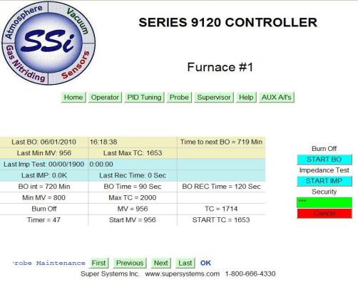
The Probe button will allow the user to view the burnoff values, as well as start a burnoff or impedance test. To make any changes, the user will have to enter the administrator web passwords first (Furnace Setup menu). To start a burnoff, click on the Start BO button. To start an impedance test, click on the Start IMP button. The screen will update with the current test’s timer and information.
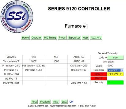
The Supervisor button will allow the user to modify the PV setpoints, the manual % on the PV, the PID parameters for both loops, as well as the alarm parameters and the burnoff parameters.
Note – The user MUST enter the administrator password to make any changes on this screen. To make any changes, the user will have to enter the administrator web passwords first (Furnace Setup menu). Note – Not all of the PID parameters are shown on the page, but all are modifiable. Once the password has been entered, select the option to modify -
Setpoint 1
Setpoint 2
Output Pwr 1 (PV 1 control percent output)
Output Pwr 2 (PV 2 control percent output)
Prop Band 1
Reset 1
Rate 1
Cycle Time 1
Integral Preset 1
High Limit 1
Low Limit 1
Prop Band 2
Reset 2
Rate 2
Cycle Time 2
Integral Preset 2
High Limit 2
Low Limit 2
Alarm Setpt
Alarm Hys
BO Interval
BO Time
BO Rec time
BO Min MV
BO Max TC
- and enter the value in the “Value” box. Note – The security box will turn green when the Set Value button is pressed and the password is correct. If it is not correct, the box will stay red. The Output Pwr 1 and Output Pwr 2 options can only be modified when the furnace PV is set to Manual. To set the PV to manual, click on the MAN 1 button for PV 1, or click on MAN 2 button for PV 2. Once the change has been made, the buttons will change to AUTO 1 or AUTO 2, as well as change color from red to green. The changes may take a few seconds to be updated on the screen.
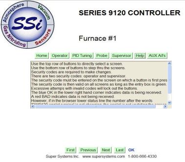
The Help button will display some general information on how to use the web page.
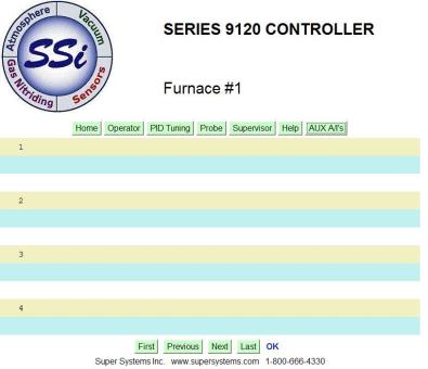
The AUX A/I’s button will display a list, if any, of the auxiliary analog inputs.
The First button will display the first screen in the list, which is the main page.
The Previous button will display the previous screen in the list.
The Next button will display the next screen in the list.
The Last button will display the last screen in the list, which is the AUX A/I’s screen.
The order of the screens is as follows:
Home
Operator
PID Tuning
Probe
Supervisor
Help
AUX A/I’s